BREAKPOINT TRIGGERS
Overview
A number of component objects are provided which trigger a suspension of the simulation when a particular circuit condition arises. These are especially useful when combined with the single stepping facilities, since the circuit can be simulated normally until a particular condition arises, and then single stepped in order to see exactly what happens next.
The whole family lives in one place in the Library Browser, under the Debugging Tools category and the Breakpoint Triggers sub-category, so it is worth browsing that page to see what is there alongside the devices described below.
Setting Up a Hardware Breakpoint
A hardware breakpoint is a mechanism by which you can pause your simulation on a hardware condition (as opposed to in software). It is extremely useful when debugging your design, particularly when an asynchronous stimulus is applied to the circuit and you need to trace or analyse its effects on the circuit.
The simplest route is through a voltage probe, which carries the breakpoint as a property. Note that this works on a voltage probe only: a current probe has no breakpoint properties, so to break on a current you must place an RTIBREAK part instead.
To set up a hardware breakpoint:
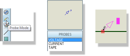
- Place a voltage probe on the wire (or bus) on which
you wish to trigger the breakpoint.
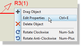
- Right click on the probe and select Edit Properties
from the context menu, or select the probe and press CTRL+E.
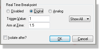
- In the Real Time Breakpoint group at the bottom of
the dialogue form, select either Digital or Analog according to the
net the probe is attached to, and specify a Trigger Value. For a digital
net and a single wire this will be either 1 or 0 corresponding to a
logic high or a logic low respectively, whereas for an analogue net
it will be a voltage value. Arm at Time, in the same group, holds the
breakpoint inactive until the simulation reaches the time you enter.
The group starts out set to Disabled, which is also how you turn a breakpoint
off again without losing the values you typed.
- Click OK, then press Run on the Animation Control Panel (or F12) to run the simulation.
Voltage Breakpoint Trigger - RTVBREAK
This device is available in 1 and 2 pinned forms, and triggers a breakpoint when the voltage at its single pin, or the voltage between its two pins, is greater than the specified value. You can couple this device to an arbitrary voltage source (AVS) to trigger a breakpoint on complex, formula-based conditions involving multiple voltages, currents and so on; the arbitrary current source (ACS) is its counterpart where the expression is best written in terms of a current.
Once the trigger voltage has been exceeded, the device does not re-trigger until the voltage has dropped below the trigger threshold and risen again.
Current Breakpoint Trigger - RTIBREAK
This device has two pins and triggers a breakpoint when the current flowing through it is greater than the specified value.
Once the trigger current has been exceeded, the device does not re-trigger until the current has dropped below the trigger threshold and risen again.
Digital Breakpoint Trigger - RTDBREAK
This device triggers a breakpoint when the binary value at its inputs equals the value assigned to the component. It ships in six widths, RTDBREAK_1, RTDBREAK_2, RTDBREAK_3, RTDBREAK_4, RTDBREAK_8 and RTDBREAK_16, alongside the single bit RTDBREAK itself, and you can make other sizes yourself if you need to. For example, specifying the value of an RTDBREAK_8 as 0x80 will cause it to trigger when D7 is high and D0 to D6 are low.
Once the trigger condition has arisen, the device does not re-trigger until a different input value has been seen.
Voltage Monitor - RTVMON
This device is available in 1 and 2 pinned forms, and acts when the input voltage falls outside the specified minimum or maximum values. By incorporating these objects into your simulator models, you can warn the end user when voltages within the model (for example the power supply voltage) exceed the specified operating limits.
What it does on a violation is set by the Trigger Action property, and the default is to raise a simulation error. The properties are:
| Property | Description |
| Input Name | The name used for this input in the message the device produces. The default is Input Voltage. |
| Minimum Voltage | The bottom of the permitted range. |
| Maximum Voltage | The top of the permitted range. |
| Trigger Action | What happens when the input leaves the range: Suspend suspends the simulation, Log records an informational message, Warn records a warning and Error raises a simulation error. Error is the default, so unless you change this property an out of range input is reported as an error rather than pausing the run. |
| Message Text | Your own wording for the message. Left empty, the device reports the input name, the value seen and the range it was expected to stay within. |
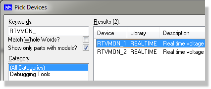
Selecting the Voltage Monitor from the Library Browser
Current Monitor - RTIMON
This device has two pins and acts when the current through the device falls outside the specified minimum or maximum values. By incorporating these objects into your simulator models, you can warn the end user when currents within the model (for example current passing through the device output terminals) exceed the specified operating limits.
Its properties are the same as those of the Voltage Monitor above, with Minimum Current and Maximum Current in place of the voltage limits, and Trigger Action again defaulting to Error.
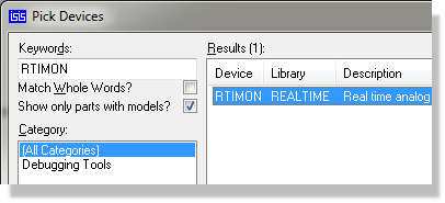
Selecting the Current Monitor from the Library Browser
RTVMON and RTIMON are the RTVCHECK and RTICHECK simulator primitives packaged as schematic parts with their properties already laid out. Both primitives can also be placed in their own right if you are building a model of your own.
See Also: